 English
 Espaol
 Franais
 阿拉伯
阿拉伯 中文
中文 Deutsch
 Italiano
 Português
 日本
日本 韓國
韓國 български
 hrvatski
 esky
esky Dansk
Dansk Nederlands
 suomi
suomi Ελληνικ
 印度
印度 norsk
norsk Polski
 Roman
Roman русский
 Svenska
Perkins珀金斯1600柴油發動機7092511 C91噴油器供應商,Perkins珀金斯1600柴油發動機7092511 C91噴油器技術價格規格咨詢服務,Perkins珀金斯1600柴油發動機7092511 C91噴油器零配件供應,Perkins珀金斯1600柴油發動機7092511 C91噴油器售后服務中心,Perkins珀金斯1600柴油發動機7092511 C91噴油器,Perkins珀金斯1600柴油發動機7092511 C91噴油器詳細的技術參數,

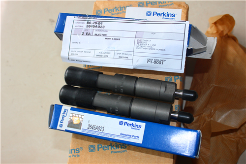
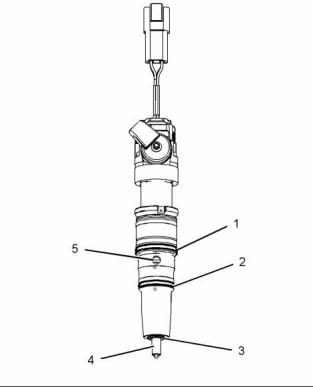
Perkins珀金斯1600柴油發動機7092511 C91噴油器
詳細描述
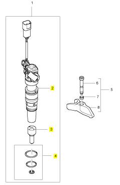
項目 零配件號碼 新件號 描述
1 7092511 C91 6 7092511 C91 噴油器裝備
5 1841843 C94 6 1841843 C94 噴油器砂箱夾
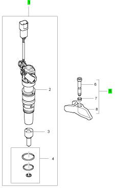
項目 零配件號碼 新件號 描述
2 1 噴油器
3 1 噴油器噴嘴
4 1842624 C92 1 1842624 C92 密封裝備
|
Water In Fuel (WIF) |
|
A Water In Fuel (WIF) sensor in the element cavity of the fuel filter housing detects water. When enough water accumulates in the element cavity, the WIF sensor signal changes to the Electronic Control Module (ECM). The ECM sends a message to illuminate the amber water and fuel lamp, alerting the operator. The WIF is installed in the base of the fuel filter housing. |
|
i04208485 |
|
Power Sources |
|
Introduction |
|
The 1600 Series industrial engine supplies power to the ECM. |
|
The ECM powers the following components: • All sensors on the engine |
|
• Electronic unit injectors |
|
ECM Power Supply |
|
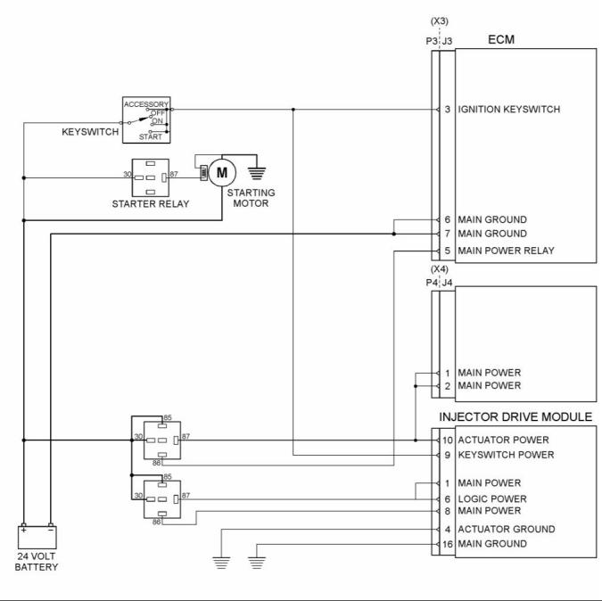
The power supply to the ECM and the system is drawn from the 24 V battery. The power supply for the ECM has the following components: |
|
This document is printed from SPI². Not for RESALE |
![]()
|
KENR8772 |
|
27 Systems Operation Section |
|
g02730797 |
|
Illustration 19 |
|
Typical example |
|
• Battery |
|
• Machine interface connector |
|
• Disconnect switch • Key start switch • Fuses |
|
The schematic for the ECM shows the main components for a typical power supply circuit. Battery voltage is supplied through a relay to the ECM. The input from the key start switch enables a relay that turns on the ECM. |
|
• Ground bolt • ECM connector |
|
The wiring harness can be bypassed for troubleshooting purposes. |
|
This document is printed from SPI². Not for RESALE |
![]()
![]()
|
28 |
|
KENR8772 |
|
Systems Operation Section |
|
The display screen on the electronic service tool can be used in order to check the voltage supply. |
|
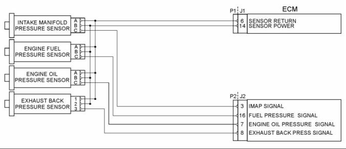
Power Supply for the Pressure Sensors |
|
g02730805 |
|
Illustration 20 |
|
A typical example of a schematic for the engine pressure sensors |
|
The ECM supplies 5.0 ± 0.2 VDC volts through the ECM connector to each sensor. The power supply is protected against short circuits. A short in a sensor or a wiring harness will not cause damage to the ECM. |
|
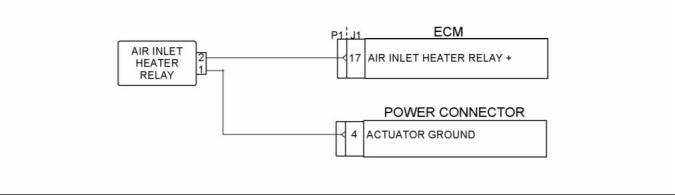
Power supply for the Air Intake Grid Heater |
|
g02730798 |
|
Illustration 21 |
|
Typical example |
|
i04031132 |
|
Fuel System |
|
This document is printed from SPI². Not for RESALE |
![]()
![]()
![]()
|
KENR8772 |
|
29 Systems Operation Section |
|
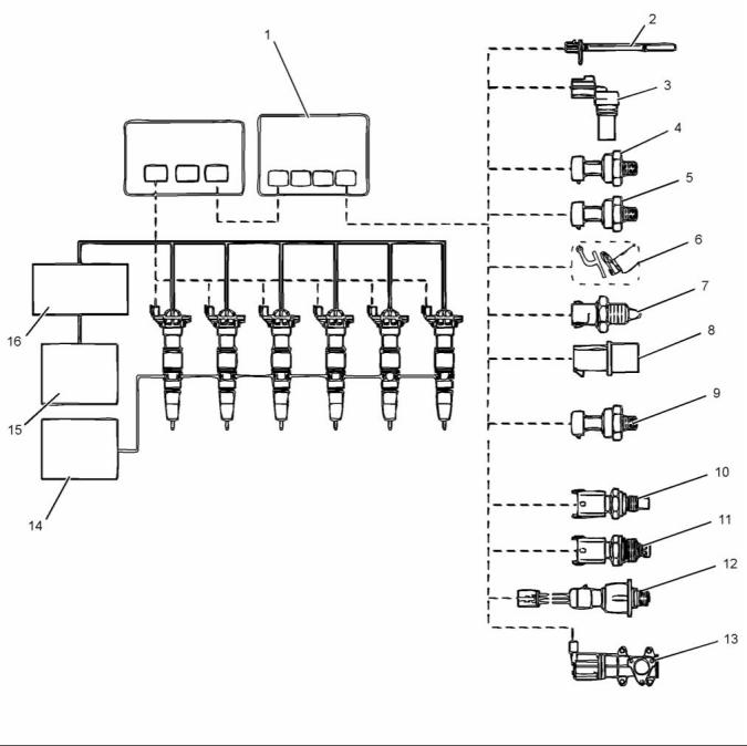
g02729237 |
|
Illustration 22 |
|
Typical example |
|
(1) Electronic Control Module (ECM) (2) Crankshaft position sensor (3) Camshaft position sensor (4) Engine oil pressure sensor (5) Manifold air pressure sensor (6) Throttle (if equipped) |
|
(7) Inlet air temperature sensor (8) Engine fuel pressure sensor (9) Exhaust back pressure sensor (10) Injector control pressure sensor (11) Engine coolant temperature sensor (12) Manifold air temperature sensor |
|
(13) Valve for the NOx Reduction System (NRS) (if equipped) (14) Fuel supply system (15) Lubrication system (16) Injection Control Pressure (ICP) system |
|
The fuel management system includes the following: • Lubrication system |
|
• Fuel injectors • Electronic control system |
|
• Injection Control Pressure (ICP) system • Fuel supply system This document is printed from SPI². Not for RESALE |
![]()
![]()
|
30 |
|
KENR8772 |
|
Systems Operation Section |
|
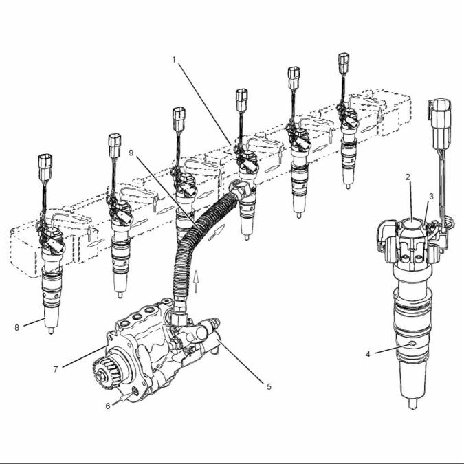
Injection Control Pressure (ICP) System |
|
g02729551 |
|
Illustration 23 |
|
Typical example |
|
(1) Unit injector actuation oil manifold (2) Injector oil inlet from Unit injector actuation oil manifold |
|
(4) Fuel inlet port |
|
(8) Electronic unit injector (9) High-pressure oil hose |
|
(5) Injection Pressure Regulator (IPR) valve (6) Oil inlet from front cover reservoir (7) Unit Injector Hydraulic Pump |
|
(3) Oil outlet |
|
This document is printed from SPI². Not for RESALE |
![]()
![]()
|
KENR8772 |
|
31 Systems Operation Section |
|
High-Pressure Oil Flow |
|
When ICP signals that are out-of-range, the ECM ignores out-of-range signals and go into open loop operation. The IPR valve will operate from programmed default values. |
|
The lubrication system constantly refills the oil reservoir located in the front cover. The reservoir provides oil for the high-pressure oil pump. The pump is mounted on the backside of the front cover and gear driven from the front of the engine. |
|
The ICP sensor is installed in the high-pressure oil manifold under the valve cover. |
|
High-pressure oil is directed to the high-pressure oil hose, cylinder head passage, and high-pressure oil manifold, which is located beneath the valve cover. |
|
Fuel Injector |
|
High-pressure oil is used by the fuel injectors to inject, pressurize, and atomize fuel in the cylinders. This occurs when the open coil for each fuel injector is energized. |
|
Excess high-pressure oil is directed to the crankcase sump by the Injection Pressure Regulator (IPR) valve. The IPR valve is controlled by the Engine Control Module (ECM) to maintain a desired injection control pressure. |
|
Injection Control Pressure (ICP) Closed Loop System |
|
The Injection Control Pressure (ICP) system is a closed loop system that uses the ICP sensor to continuously provide injection control pressure feedback to the ECM. The ECM commands the IPR duty cycle to adjust ICP pressure to match engine requirements. |
|
Injection Control Pressure (ICP) Control System |
|
The Injection Pressure Regulator (IPR) solenoid receives a pulse-width modulated signal from the ECM. This indicates the on and off time the IPR control valve is energized. The pulse is calibrated to control ICP pressure which ranges from 5 MPa (725 psi) up to 32 MPa (4641 psi). |
|
g02729963 |
|
Illustration 24 |
|
Typical example |
|
(1) Upper O-ring (2) Lower O-ring (3) Combustion washer (4) Injector nozzle (5) Fuel inlet port |
|
The IPR valve is mounted in the body of the high-pressure pump. The IPR valve maintains desired injection control pressure by dumping excess oil back to the crankcase sump. |
|
Two 48V, 20 amp coils control a spool valve that directs oil flow in and out of the injector. The injector coils are turned on for approximately 800 (microseconds). Each injector has a single four pin connector that couples to the valve cover gasket assembly. |
|
As demand for injection control pressure increases, the ECM increases the pulse-width modulation to the IPR solenoid. When demand for injection control pressure decreases, the duty cycle to the IPR solenoid decreases and more oil is allowed to flow to the drain orifice. |
|
An open coil and a close coil on the injector move the spool valve from side to side using magnetic force. The spool has two positions: |
|
When the injection control pressure electrical signal is out-of-range, the ECM sets a Diagnostic Trouble Code (DTC). The ECM will not set DTCs if an injection control pressure signal corresponds to an in-range valve for injection control pressure for a given operating condition. |
|
• • |
|
When the spool valve is open, oil flows into the injector from the high-pressure oil manifold. |
|
When the spool valve is closed, oil exits from the top of the fuel injector and drains back to the crankcase. |
|
This document is printed from SPI². Not for RESALE |
![]()
![]()
|
32 |
|
KENR8772 |
|
Systems Operation Section |
|
When the spool valve is open, high-pressure oil enters the injector pushing down the intensifier piston and plunger. Since the intensifier piston is 7.6 times greater in surface area than the plunger, the injection pressure is also 7.6 times greater than injection control pressure on the plunger. |
|
Fuel pressure builds at the base of the plunger in the barrel. When the intensifier piston pushes the plunger down, the plunger increases fuel pressure in the barrel 7.6 times greater than injection control pressure. The plunger has a hardened coating to resist scuffing. |
|
The injector needle opens inward when fuel pressure overcomes the Valve Opening Pressure (VOP) of 28 MPa (4061 psi). Fuel is injected at high pressure through the nozzle tip. |
|
Fuel Injector Operation The injector operation has three stages: • Fill stage |
|
• Injection |
|
• End of injection |
|
g02729965 |
|
Illustration 25 |
|
Typical example |
|
(1) Oil inlet from rail (2) Coil (3) Spool (4) Plunger (5) Barrel (6) Needle (7) Nozzle holes (8) Nozzle (9) Fuel inlet (10) Intensifier piston (11) Coil |
|
Fill Stage |
|
During the fill stage both coils are de-energized and the spool valve is closed. High-pressure oil from the high-pressure oil manifold is stopped at the spool valve. |
|
Low-pressure fuel fills the four ports and enters through the edge filter on the way to the chamber beneath the plunger. The needle control spring holds the needle onto the seat to prevent fuel from entering the combustion chamber. |
|
This document is printed from SPI². Not for RESALE |